Remote Alarm
Remote sensors station with 433 MHz trasmitter
I have something, that is about 30m from my home and I want to watch it. There is not cable connection, so I decided to make wireless alarm station that uses 433 MHz connection
Schema, function description
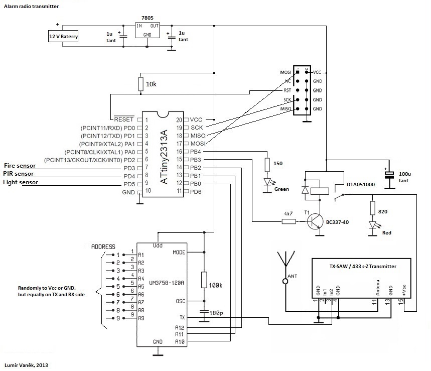
ATtiny2313A periodically checks three inputs PD3 - 5, where are PIR, light and fire sensors connected. In case that alarm is signaled, relay switch ON transmitter. UM3758-120A is coder/decoder, that have 3-state inputs, that's used for pairing transmitter with receiver - both must have set this same code on A1 - A12 inputs. So last 3 ones: A10 - A12 I use for signaling 8 alarm types. Remote alarm uses 4, others are reserved for future use:
| A10 | A11 | A12 | Signal |
|---|---|---|---|
| 0 | 0 | 0 | Watchdog |
| 0 | 0 | 1 | Fire alarm |
| 0 | 1 | 0 | PIR alarm |
| 0 | 1 | 1 | Light alarm |
When no activity occurred, green LED blinks and watchdog is periodically signaled.
Developing
For developing, I use breadboard and following tools:
- Atmel Studio - IDE for developing and debugging Atmel CPU's
- AVRDUDE - utility to download/upload/manipulate the ROM and EEPROM contents of AVR microcontrollers
- avrdude-GUI - GUI for avrdude
- AVR USBasp - USB in-circuit programmer for Atmel AVR

AVR USBasp is great tool - it allow insert many types of ATxxx family CPU's into socket and load program into it. There are pins that allow connect CPU to breadboard and develop circuit and software in flexible way. Finally, circuit can be moved to PCB.
Source code
Software is very simple: in infinite loop, sensors (PD3 - 5 inputs) are checked and when alarm is signaled, proper code is set to PB0 - 3 outputs (alarm code) and also PB3 switch relay ON for 10 seconds to give time for receiver to scan it. When no alarm occurred, watchdog signal is send every 50 green LED blinks.
Construction
Construction is on universal board, housed in ABS plastic box.
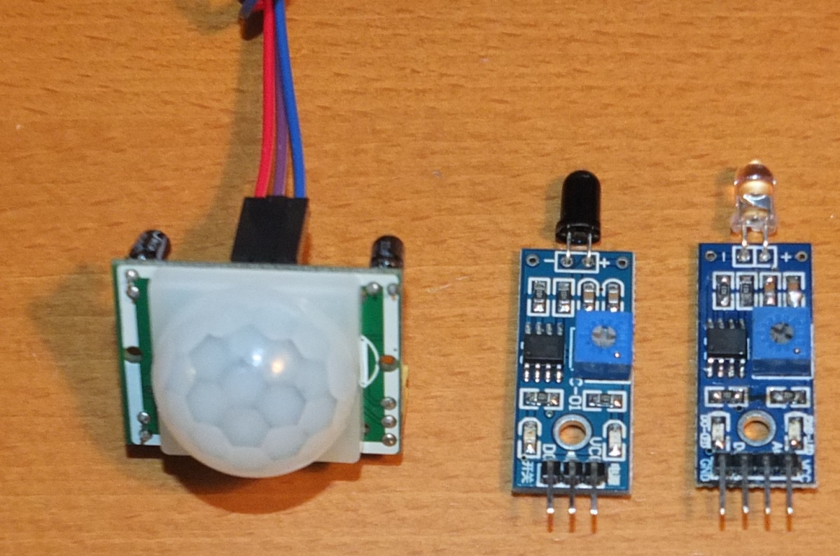 PIR, fire and light sensors |
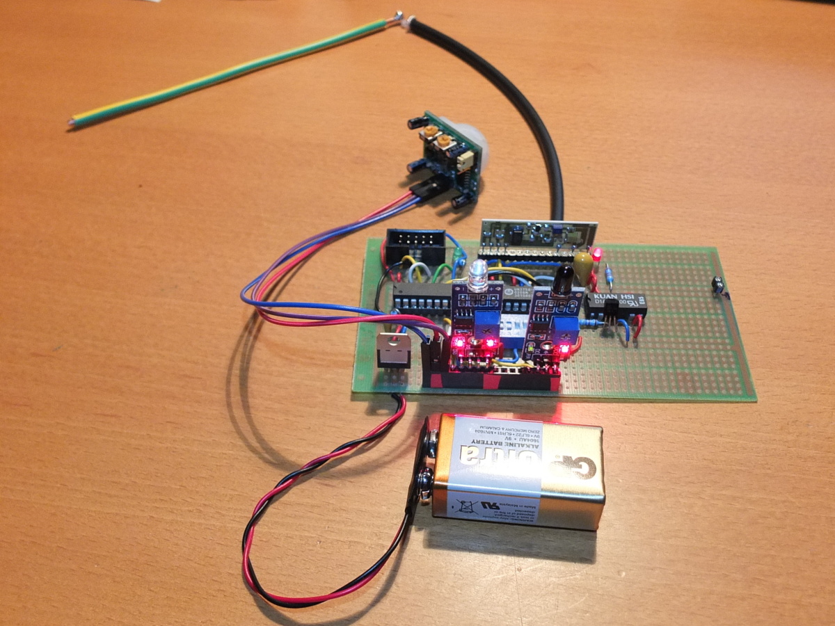 PCB testing |
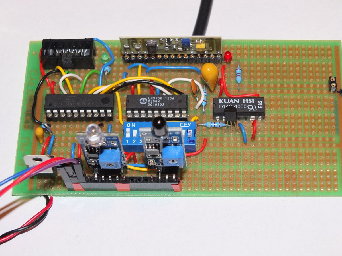 PCB detail |
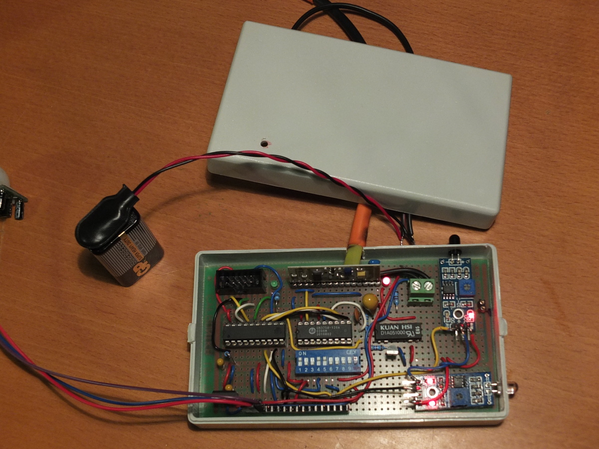 Final |
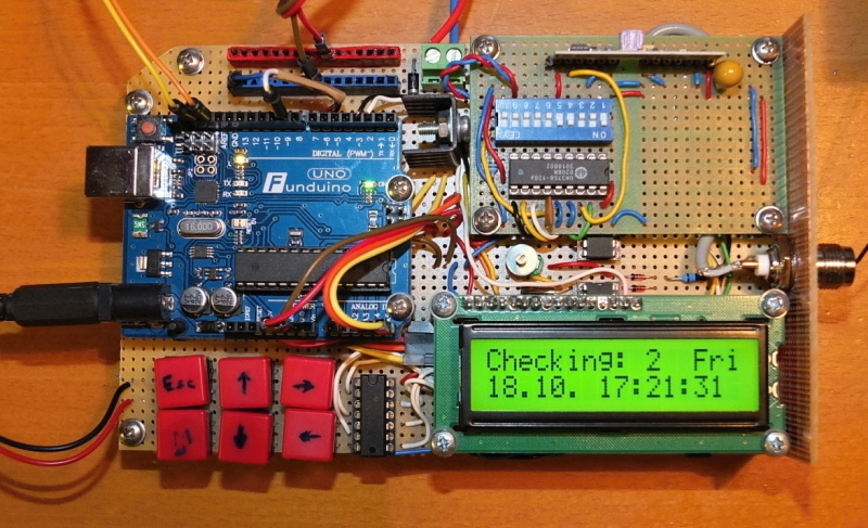
Arduino Uno base station with 433 MHz receiver
Base station is used for alarm signalling and also for playing and learning.
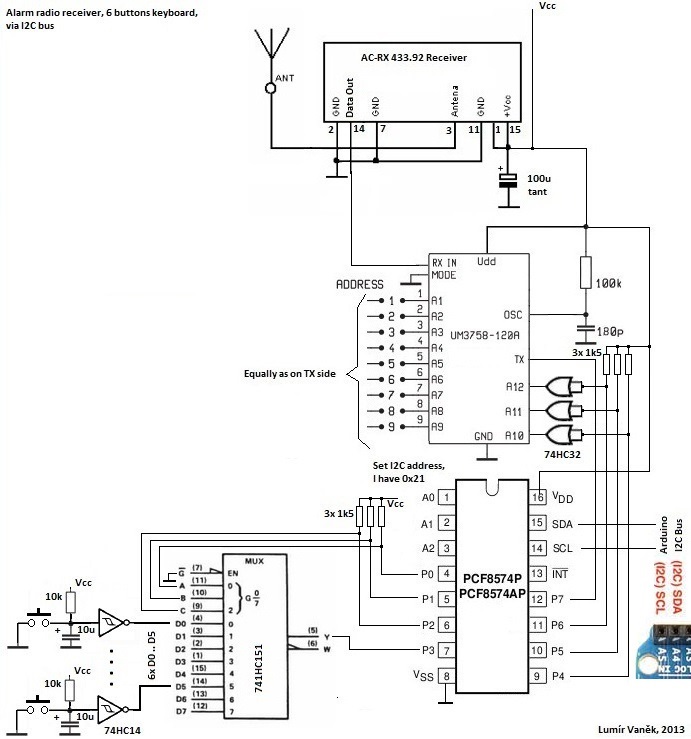
Schema, function description
This schema contains 6-button keyboard and radio receiver for remote alarm. PCF8574, the I²C 8-bit expander is used for adressing 74HC151, that scans buttons. Also UM3758-120A decoder A10 - A12 inputs allows scan 8 alarm codes from 433 MHz radio receiver.
Construction
Construction is on universal board, it's not like final product, rather used for learning and playing in future
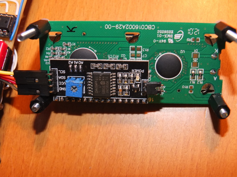 16x2 LCD, driven by PCF8574T |
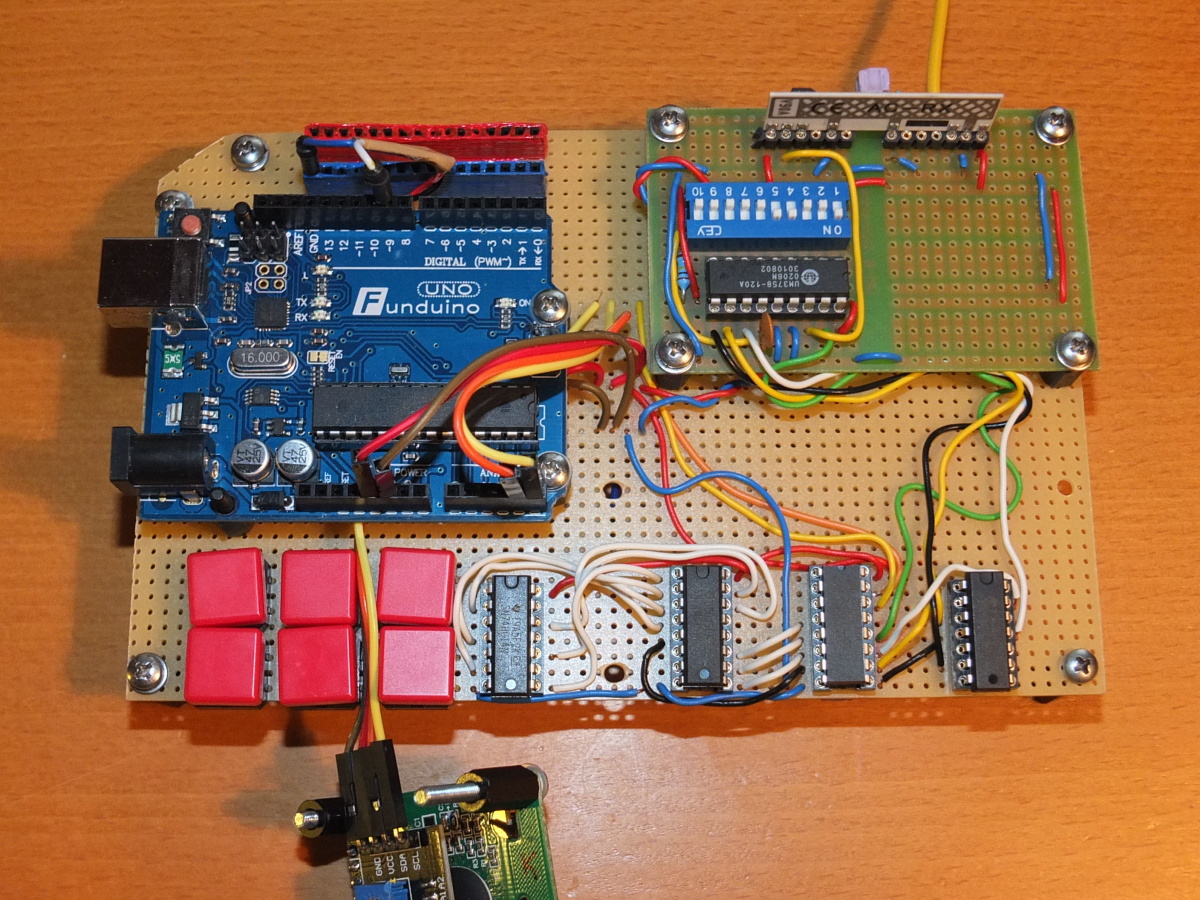 Main unit |
On base PCB, there is 6-button keyboard with related logic, 16x2 LCD with I²C interface and piezzo buzzer. 433 MHz radio receiver and decoder is on dedicated PCB module.
Software
Base station software I develop using Arduino IDE. This code contains alarm logic, and aditionaly there are routines for playing with PCF8583 (I²C RTC), PCF8574 (I²C 8-bit expander) and PCF8591 (I²C 8-bit A/D and D/A converter). For this reason, following source code is not complete, here is only keyboard, LCD and alarm related code.
Sketch download.